ImageProjection in LeGO-LOAM (1) Range Image Projection & Ground Removal
imageProjection.cpp에서는 3D LiDAR sensor로 취득한 point cloud를 range image로 projection을 한 후에, preprocessing을 진행한다. 그로 인해, 3D point cloud 상의 각 포인트를 segmentedCloud와 outlierCloud로 binary classification을 진행한다. 요약하자면, imageProjection.cpp의 역할은 아래와 같이 세 가지로 꼽을 수 있다.
- Image Projection의 다은 단계인 Feature Association에서 interpolation을 할 때 파라미터로 사용되는
segMsg.orientationDiff미리 세팅 - Ground points/Non-ground points 구분
- Ground points: Laser ray가 땅바닥에서 반사되어 측정된 point로, 주로 3D point cloud 상에서 50~60%는 ground points임. 따라서 미리 ground points를 거르면 후과정에서의 연산량을 줄일 수 있음
- Non-ground points 상에서 유효한 segment와 그렇지 않은 것들로 포인트를 구분함
- 다소 noisy한 points들: Sub-cluster라고도 부르는데, clustering을 했더니 너무 포인트 수가 적은 cloud points들. 덤불(bushes)같이 기하학적으로 비정형적인 물체들을 제거하는 것을 목표로 함.
요약하자면 featureAssociation.cpp에서 feature를 추출하기 이전에 preprocessing을 해주는 단계라고 볼 수 있다. Preprocessing을 위해 a) ground points와 b) 주변 환경을 잘 묘사할 수 있는 (reliable & repeatable) non-ground points를 raw point cloud에서 추출해낸다.
Overview
각 frame마다 3D LiDAR sensor에서 3D point cloud를 측정하면 아래와 같은 cloudHandler callback이 실행되고, 아래와 같이 7 단계로 구성되어 있다.
void cloudHandler(const sensor_msgs::PointCloud2ConstPtr& laserCloudMsg){
    // 1. Convert ros message to pcl point cloud
    copyPointCloud(laserCloudMsg);
    // 2. Start and end angle of a scan
    findStartEndAngle();
    // 3. Range image projection
    projectPointCloud();
    // 4. Mark ground points
    groundRemoval();
    // 5. Point cloud segmentation
    cloudSegmentation();
    // 6. Publish all clouds
    publishCloud();
    // 7. Reset parameters for next iteration
    resetParameters();
}
핵심 변수들
Decision making을 위한 내부 멤버 변수들
Step 4와 5에서 각 point의 상태를 판별하는 게 조금 헷갈리는데, 미리 정리를 하자면 아래와 같다 (코드를 보다가 해당하는 변수의 값이 뭘 나타내는지 헷갈릴 때 참고).
크게 이 preprocessing 단계에서 가장 중요한 변수는 아래와 같은 세 개의 matrix이다.
cv::Mat rangeMat; // range matrix for range image
cv::Mat labelMat; // label matrix for segmentaiton marking
cv::Mat groundMat; // ground matrix for ground cloud marking
각 matrix의 각 값은 아래와 같다 matrix의 status를 #define을 통해서 정의해줬으면 이해하기 편했을텐데…
rangeMat: 3D Point cloud를 range image로 만들 때 쓰임FLT_MAX로 initialization- 한 point가 pixel에 해당하면 센서 프레임으로부터 그 point까지의 거리로 채워짐
groundMat: Range image의 pixel과 일대일 대응되며, range image 중에서 ground points들을 masking하는 용도로 사용- 0으로 initialization. 그 후, non-ground의 label로 사용됨
- -1: 유효하지 않은 값으로 인해 ground인지 non-ground인지 여부를 판단할 수 없음을 의미. 즉 해당 pixel과 대응되는
rangeMat상의 값이FLT_MAX일 때 - 1: Ground로 판명
labelMat: Range image의 pixel과 일대일 대응되며, range image 중에서 non-ground points들 중 valid segment를 masking하는 용도로 사용- 0으로 initialization됨. 0은 Not assigned를 의미함
- -1: 해당하는 pixel의 위치가 유효하지 않다고 판별됐을 때. 즉, 해당하는 pixel과 대응되는
groundMat상의 값이 1이거나,rangeMat상의 값이FLT_MAX일 때 - 1 이상: label이 유효하면 1 이상의 값이 할당됨.
labelComponents(i, j)함수에서 시행. 즉, 0 초과인 값들은 모두 유효한 값. Cluster의 id를 나타냄 - 999999:
labelComponents(i, j)함수에서 clustering을 한 후 cluster의 point 수가 너무 적은 경우. Ground는 아니지만 유효하지 않다는 것을 의미함
추가적으로, 이러한 matrix들과 fullCloud, fullInfoCloud는 아래와 같이 initialization이 된다.
// in `allocateMemory()`
fullCloud->points.resize(N_SCAN*Horizon_SCAN);
fullInfoCloud->points.resize(N_SCAN*Horizon_SCAN);

// in `resetParameters()`
rangeMat = cv::Mat(N_SCAN, Horizon_SCAN, CV_32F, cv::Scalar::all(FLT_MAX));
groundMat = cv::Mat(N_SCAN, Horizon_SCAN, CV_8S, cv::Scalar::all(0));
labelMat = cv::Mat(N_SCAN, Horizon_SCAN, CV_32S, cv::Scalar::all(0));

std::fill(fullCloud->points.begin(), fullCloud->points.end(), nanPoint);
std::fill(fullInfoCloud->points.begin(), fullInfoCloud->points.end(), nanPoint);
여기서 nanPoint는 아래와 같이 정의되어 있는데,
nanPoint.x = std::numeric_limits<float>::quiet_NaN();
nanPoint.y = std::numeric_limits<float>::quiet_NaN();
nanPoint.z = std::numeric_limits<float>::quiet_NaN();
nanPoint.intensity = -1;
그래서 향후에 fullCloud->points의 각 point의 intensity가 -1인지 아닌지를 판별하여 현재 상태가 유효한지 아닌지를 판별한다 (물리적으로 intensity가 음수의 값으로 나오지는 않기 때문. step 4. groundRemoval() 참조)
최종 output message
최종적으로, featureAssociation.cpp의 입력값으로 되는 segMsg는 아래와 같은 멤버 변수를 지니고 있고, 연산 효율성을 위해 fixed size로 정의되어 있다.
segMsg.startRingIndex.assign(N_SCAN, 0);
segMsg.endRingIndex.assign(N_SCAN, 0);

segMsg.segmentedCloudGroundFlag.assign(N_SCAN*Horizon_SCAN, false);
segMsg.segmentedCloudColInd.assign(N_SCAN*Horizon_SCAN, 0);
segMsg.segmentedCloudRange.assign(N_SCAN*Horizon_SCAN, 0);
copyPointCloud(laserCloudMsg);는 이름에서 알 수 있듯이 point cloud를 복사하는 행위이기 때문에 생략한다.
2. findStartEndAngle();
void findStartEndAngle(){
    // start and end orientation of this cloud
    segMsg.startOrientation = -atan2(laserCloudIn->points[0].y, laserCloudIn->points[0].x);
    segMsg.endOrientation   = -atan2(laserCloudIn->points[laserCloudIn->points.size() - 1].y,
                                                 laserCloudIn->points[laserCloudIn->points.size() - 1].x) + 2 * M_PI;

    if (segMsg.endOrientation - segMsg.startOrientation > 3 * M_PI) {
        segMsg.endOrientation -= 2 * M_PI;
    } else if (segMsg.endOrientation - segMsg.startOrientation < M_PI)
        segMsg.endOrientation += 2 * M_PI;
    segMsg.orientationDiff = segMsg.endOrientation - segMsg.startOrientation;
}
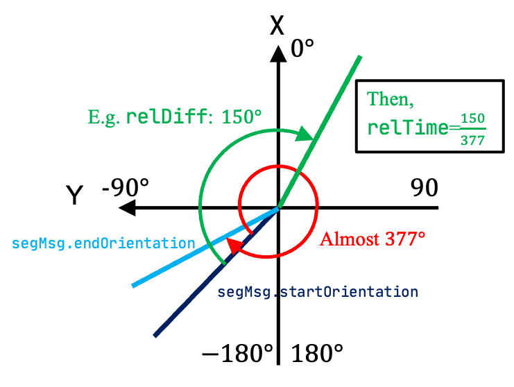
이 행위를 통해 3D LiDAR sensor가 0.1초 동안 회전한 총 angle을 구한다. 실제로 Velodyne Puck LiDAR를 사용했을 경우 (segMsg.startOrientation, segMsg.endOrientation)를 cout으로 출력해보면 연속적으로 (-118.59, 259.08), (-100.85, 276.93), (-82.98, 294.76), (-65.16, 312.58) (-47.33, 330.62), (-29.3, 348.7), (-11.22, 366.56), (6.66, 384.53), (24.63, 402.56), (42.61, 420.44), (60.51, 438.03), (78.08, 455.49) … 과 같이 약 17도 정도 shift가 일어나면서 0.1초당 377도를 측정하게끔 세팅이 되어있다 (이러한 세팅은 변경할 수 있기 때문에, 알잘딱깔센으로 확인해봐야 한다). 이 차이각, i.e. 377도,은 segMsg.orientationDiff에 저장된다 (단위: rad).
그런데, 여기서 왜 ‘-‘atan2()로 구하지???라는 의문이 들텐데, 이는 Velodyne Puck의 경우 ROS 상에서 point cloud를 입력으로 받았을 때, 0~N개의 point들이 아래와 같이 시계 방향 순으로 (clock-wise) vector에 담겨있기 때문이다.

이렇게 세팅된 변수들은 아래와 같이 featureAssociation.cpp에서 각 포인트의 상대적인 시간, i.e. 위 그림 상의 relTime,을 계산할 때 사용된다. 아래와 같이 N개의 points 중 n번 째의 point와 가장 처음 취득한 포인트와의 차이각 대비 총 차이각의 비율을 구하여 relTime을 구할 수 있는데,
// adjustDistortion() in featureAssociation.cpp
float relTime = (ori - segInfo.startOrientation) / segInfo.orientationDiff;
point.intensity = int(segmentedCloud->points[i].intensity) + scanPeriod * relTime;
여기서 ori는 각 point의 각도를 뜻하며, scanPeriod는 주로 0.1초이기 때문에 0초~0.1초 사이에 해당 포인트가 취득된 시각을 각도를 통해 역추적할 수 있다. 이는 point cloud를 deskewing할 때 활용된다 (향후 Feature Association에서 다시 설명 예정).
3. projectPointCloud()
그 후, N개(아래의 cloudSize)의 points를 가상의 range image, i.e. rangeMat,로 projection시킨다. 이 때, 3D point cloud를 N_SCANxHorizon_SCAN의 array로 매핑한다. Velodyne 16의 경우에는 matrix의 사이즈가 16 (channel 갯수)x1800 (수평한 방향으로 각 channel에서 취득할 수 있는 갯수, i.e. 360 deg/ang_res_x)와 같다. 순서대로 각 point의 rowIdn와 columnIdn pixel 위치를 구하고, 해당하는 픽셀 (rowIdn, columnIdn)에 range 값을 저장한다.
void projectPointCloud(){
    // range image projection
    float verticalAngle, horizonAngle, range;
    size_t rowIdn, columnIdn, index, cloudSize;
    PointType thisPoint;

    cloudSize = laserCloudIn->points.size();

    for (size_t i = 0; i < cloudSize; ++i){

        thisPoint.x = laserCloudIn->points[i].x;
        thisPoint.y = laserCloudIn->points[i].y;
        thisPoint.z = laserCloudIn->points[i].z;
        // find the row and column index in the iamge for this point
        if (useCloudRing == true){
            rowIdn = laserCloudInRing->points[i].ring;
        }
        else{
            verticalAngle = atan2(thisPoint.z, sqrt(thisPoint.x * thisPoint.x + thisPoint.y * thisPoint.y)) * 180 / M_PI;
            rowIdn = (verticalAngle + ang_bottom) / ang_res_y;
        }
        if (rowIdn < 0 || rowIdn >= N_SCAN)
            continue;

        horizonAngle = atan2(thisPoint.x, thisPoint.y) * 180 / M_PI;

        columnIdn = -round((horizonAngle-90.0)/ang_res_x) + Horizon_SCAN/2;

        if (columnIdn >= Horizon_SCAN)
            columnIdn -= Horizon_SCAN;

        if (columnIdn < 0 || columnIdn >= Horizon_SCAN)
            continue;

        range = sqrt(thisPoint.x * thisPoint.x + thisPoint.y * thisPoint.y + thisPoint.z * thisPoint.z);
        if (range < sensorMinimumRange)
            continue;

        rangeMat.at<float>(rowIdn, columnIdn) = range;

        thisPoint.intensity = (float)rowIdn + (float)columnIdn / 10000.0;

        index = columnIdn  + rowIdn * Horizon_SCAN;
        fullCloud->points[index] = thisPoint;
        fullInfoCloud->points[index] = thisPoint;
        fullInfoCloud->points[index].intensity = range; // the corresponding range of a point is saved as "intensity"
    }
}
다른 부분들은 Introduction의 3D LiDAR sensor의 특성을 이해하면 다 자명한데, columIdn 부분이 다소 헷갈리게 되어있다. 왜냐하면 C++에서 atan2는 (y, x)로 사용하게 되어 있는데 range image의 columnIdn을 구할 때는 atan2(x, y)로 사용하기 때문이다. 좀 더 이해를 돕기 위해, 각 각도에 따라 대응하는 값들을 아래와 같이 정리해보았다.

여기서 뒷쪽의 index를 0으로 둔 원저자 Tixiao님의 디테일이 보인다. LeGO-LOAM에서 feature를 추출하는 과정에서 0과 1799 index가 서로 붙어 있음에도 피쳐를 추출하지 않는데, feature로서 사용이 안 될 수도 있는 부분을 뒷쪽으로 둚으로써 양옆과 앞쪽에서는 feature를 잘 뽑을 수 있게 세팅해둔 것이다. 모바일 로봇의 경우에는 주로 pilot이 뒤쪽에서 조종을 하다보니, 뒷쪽 point cloud를 버리는 경우가 많고, 자율차의 경우에도 보닛이 point cloud의 뒷쪽에 찍혀서 앞의 180도만 쓰는 경우가 있는데, 이 관점에서 봤을 때 index의 시작점을 motion direction의 뒤쪽에 두는 것은 나름 효율적인 선택인 것 같다 (100% 저의 주관적인 견해입니다).
4. groundRemoval()
Range image를 만든 후에, range image를 활용하여 ground points를 labeling한다. 이 과정에서는 암묵적으로 3D LiDAR sensor가 수평하게 모바일 플랫폼에 부착되어 있다고 가정한다. 그렇기 때문에 16 channel LiDAR의 경우 1~8번째 channel의 경우에만 땅바닥쪽으로 laser ray가 방출되고 있기 때문에, groundScanInd=7, sensorMountAngle=0 (deg)로 세팅한 것을 볼 수 있다.
(주의: Velodyne HDL series의 경우 바닥쪽으로 laser ray가 약간 치우쳐져 있는 sensor들도 존재한다, e.g. Velodyne HDL-32E or Velodyne HDL-64E. 따라서 무지성으로 # of channels/2으로 groundScanInd를 세팅하면 안 되고 datasheet를 꼭 확인 후 하드웨어 맞게 세팅해야한다!!)
전체 코드는 아래와 같고, 해당하는 부분을 설명할 때 이해를 돕기 위해 그림을 첨부한다.
void groundRemoval(){
    size_t lowerInd, upperInd;
    float diffX, diffY, diffZ, angle;
    // groundMat
    // -1, no valid info to check if ground of not
    //  0, initial value, after validation, means not ground
    //  1, ground
    for (size_t j = 0; j < Horizon_SCAN; ++j){
        for (size_t i = 0; i < groundScanInd; ++i){

            lowerInd = j + ( i )*Horizon_SCAN;
            upperInd = j + (i+1)*Horizon_SCAN;

            if (fullCloud->points[lowerInd].intensity == -1 ||
                fullCloud->points[upperInd].intensity == -1){
                // no info to check, invalid points
                groundMat.at<int8_t>(i,j) = -1;
                continue;
            }

            diffX = fullCloud->points[upperInd].x - fullCloud->points[lowerInd].x;
            diffY = fullCloud->points[upperInd].y - fullCloud->points[lowerInd].y;
            diffZ = fullCloud->points[upperInd].z - fullCloud->points[lowerInd].z;

            angle = atan2(diffZ, sqrt(diffX*diffX + diffY*diffY) ) * 180 / M_PI;

            if (abs(angle - sensorMountAngle) <= 10){
                groundMat.at<int8_t>(i,j) = 1;
                groundMat.at<int8_t>(i+1,j) = 1;
            }
        }
    }
    // extract ground cloud (groundMat == 1)
    // mark entry that doesn't need to label (ground and invalid point) for segmentation
    // note that ground remove is from 0~N_SCAN-1, need rangeMat for mark label matrix for the 16th scan
    for (size_t i = 0; i < N_SCAN; ++i){
        for (size_t j = 0; j < Horizon_SCAN; ++j){
            if (groundMat.at<int8_t>(i,j) == 1 || rangeMat.at<float>(i,j) == FLT_MAX){
                labelMat.at<int>(i,j) = -1;
            }
        }
    }
    if (pubGroundCloud.getNumSubscribers() != 0){
        for (size_t i = 0; i <= groundScanInd; ++i){
            for (size_t j = 0; j < Horizon_SCAN; ++j){
                if (groundMat.at<int8_t>(i,j) == 1)
                    groundCloud->push_back(fullCloud->points[j + i*Horizon_SCAN]);
            }
        }
    }
}

정리하자면, ground removal은 크게 아래의 세 단계로 이루어진다.
a) Check the validity of the values in the range image
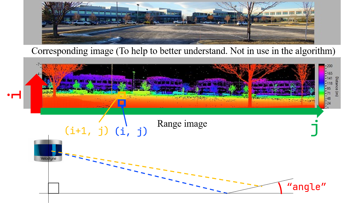
먼저 range image 상에서 row 방향으로 위쪽 (i+1, j)과 아래쪽 (i, j) 인덱스를 세팅한 후, 해당하는 픽셀에 projectPointCloud() 함수를 통해 유효한 range 값이 할당되었는지를 우선 체크한다. 아래에서 intensity가 -1이란 말은, (rowIdn, columnIdn)에 대응하는 부분에 유효한 range 값이 projection 되지 않아서 계속 nanPoint로 할당되어 있음을 뜻한다. 그냥 rangeMat 상의 값이 FLT_MAX인지 아닌지를 확인하는 게 더 직관적인 거 같은데…
따라서 둘 중 하나라도 range 값이 할당되어 있지 않으면 groundMat의 픽셀 (i, j)에 -1 (판별할 수 없음)을 할당하고 아래 추가적인 판단은 skip한다.
if (fullCloud->points[lowerInd].intensity == -1 ||
    fullCloud->points[upperInd].intensity == -1){
    // no info to check, invalid points
    groundMat.at<int8_t>(i,j) = -1;
    continue;
}
b) Check the inter-ring gradient
만약 두 값 모두 유효한 measurement가 있다면, 그 두 값의 gradient를 아래와 같이 측정한다 (위의 그림 상의 angle 참조). 그리고 그 값이 10도 이내이면(위의 그림과 같이 두 ray가 이루는 각도가 작으면 충분히 평평하다는 뜻) groundMat의 픽셀 (i, j)에 1 (해당 픽셀들은 ground임)을 할당한다.
diffX = fullCloud->points[upperInd].x - fullCloud->points[lowerInd].x;
diffY = fullCloud->points[upperInd].y - fullCloud->points[lowerInd].y;
diffZ = fullCloud->points[upperInd].z - fullCloud->points[lowerInd].z;

angle = atan2(diffZ, sqrt(diffX*diffX + diffY*diffY) ) * 180 / M_PI;

if (abs(angle - sensorMountAngle) <= 10){
    groundMat.at<int8_t>(i,j) = 1;
    groundMat.at<int8_t>(i+1,j) = 1;
}
c) Mask the pixels which are considered as the ground or have invalid values
Ground masking을 다 한 후, i) groundMat에서 ground로 판별되었거나 ii) point가 projection되지 않아서 rangeMat의 값이 FLT_MAX인 경우 labelMat에 -1을 할당한다.
-1로 할당된 pixel들은 Step 5. cloudSegmentation() 함수 과정에서 제외된다.
for (size_t i = 0; i < N_SCAN; ++i){
     for (size_t j = 0; j < Horizon_SCAN; ++j){
         if (groundMat.at<int8_t>(i,j) == 1 || rangeMat.at<float>(i,j) == FLT_MAX){
             labelMat.at<int>(i,j) = -1;
         }
     }
 }
Supplementary materials: Ground segmentation module in LeGO-LOAM vs Patchwork
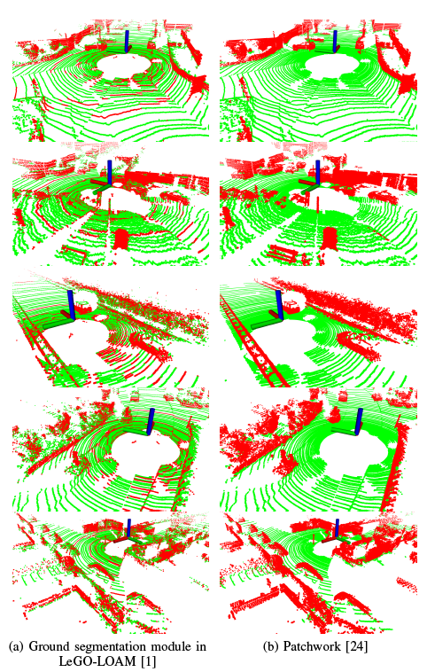
혹시 이 글을 읽는 이들 중 순수히 ground segmentation를 목적으로 알아보다가 LeGO-LOAM의 내부 모듈을 살펴보고 있는 것이라면, 그리 추천하지 않는다. 왜냐하면 LeGO-LOAM의 ground segmentation module을 활용하여 ground segmentation을 하면 아래 그림과 같이 실제 ground points가 ground로 segmentation되지 않는 현상이 나타나는데, 이러한 현상은 두 가지로 설명할 수 있다. (초록색: estimated ground points, red: estimated non-ground points)
- Range image라는 제한된 resolution으로 ground segmentation을 하다보니, 한 픽셀 내에 여러 points가 찍히는 경우에 대해서는 실제 ground points가 ground로 판별이 되지 않음
- Line 기반이다보니, 수풀같이 기울기가 다소 불규칙적인 지역에서는 ground segmentation 성능이 상당히 저하됨
따라서, ground segmentation 자체에 관심이 있는 것이라면 Patchwork를 추천한다! 아래 그림은 빨간색이 estimated non-ground points, 초록색이 estimated ground points를 의미한다.
LeGO-LOAM의 line-by-line 설명 시리즈입니다.
- LeGO-LOAM-Line-by-Line-1.-Introduction: Preview and Preliminaries
- LeGO-LOAM-Line-by-Line-2.-ImageProjection-(1): Range Image Projection & Ground Removal
- LeGO-LOAM-Line-by-Line-2.-ImageProjection-(2): Cloud Segmentation using Clustering
- LeGO-LOAM-Line-by-Line-3.-FeatureAssociation-(1): Ready for Feature Extraction
- LeGO-LOAM-Line-by-Line-3.-FeatureAssociation-(2): Corner and Planar Feature Extraction
- LeGO-LOAM-Line-by-Line-3.-FeatureAssociation-(3): Relative Pose Estimation via Two-stage Optimization
