FeatureAssociation in LeGO-LOAM (1) Ready for Feature Extraction
featureAssociation.cpp에서 역할은 크게 두 가지이다. 먼저 a) imageProjection.cpp에서 추출한 segmented cloud를 입력으로 받아 해당하는 point cloud로부터 유의미한 corner feature와 edge feature를 뽑고, b) t-1과 t 사이의 relative odometry를 각 feature로부터 추정한다. 즉, LiDAR odometry에 대응되는 가장 중요한 파트라고 볼 수 있다 😎.
Overview
먼저 전체적으로 아래와 같이 200Hz로 (>10Hz) runFeatureAssociation() 함수를 계속 시행한다.
int main(int argc, char** argv)
{
    ros::init(argc, argv, "lego_loam");

    ROS_INFO("\033[1;32m---->\033[0m Feature Association Started.");

    FeatureAssociation FA;

    ros::Rate rate(200);
    while (ros::ok())
    {
        ros::spinOnce();

        FA.runFeatureAssociation();

        rate.sleep();
    }

    ros::spin();
    return 0;
}
그리고 runFeatureAssociation() 함수는 아래와 같이 네 파트로 구성되어 있다.
void runFeatureAssociation()
{
    /**
     1. Check whether the output of ImageProjection is coming or not
    */
    if (newSegmentedCloud && newSegmentedCloudInfo && newOutlierCloud &&
        std::abs(timeNewSegmentedCloudInfo - timeNewSegmentedCloud) < 0.05 &&
        std::abs(timeNewOutlierCloud - timeNewSegmentedCloud) < 0.05){

        newSegmentedCloud = false;
        newSegmentedCloudInfo = false;
        newOutlierCloud = false;
    }else{
        return;
    }
    /**
     2. Ready for Feature Extraction
    */
    adjustDistortion();

    calculateSmoothness();

    markOccludedPoints();

    /**
     3. Corner and Planar Feature Extraction
    */
    extractFeatures();

    publishCloud(); // cloud for visualization

    if (!systemInitedLM) {
        checkSystemInitialization();
        return;
    }

    /**
     4. Relative Pose Estimation via Feature Association
    */
    updateInitialGuess();

    updateTransformation();

    integrateTransformation();

    publishOdometry();

    publishCloudsLast(); // cloud to mapOptimization
}
1. Check whether the output of ImageProjection is coming or not
가장 첫 번째로 FeatureAssociation으로 입력값들이 다 callback을 통해 할당이 완료되었는지 확인한다.
if (newSegmentedCloud && newSegmentedCloudInfo && newOutlierCloud &&
    std::abs(timeNewSegmentedCloudInfo - timeNewSegmentedCloud) < 0.05 &&
    std::abs(timeNewOutlierCloud - timeNewSegmentedCloud) < 0.05){

    newSegmentedCloud = false;
    newSegmentedCloudInfo = false;
    newOutlierCloud = false;
}else{
    return;
}
3D LiDAR sensor의 Hz가 10Hz임을 감안하면, 0.05 sec.의 timestamp 간격이 상당히 작다는 것을 알 수 있다. 그렇더라도 ImageProjection단에서 거의 동시에 세 개의 message를 publish하기 때문에 서로간의 time delay가 적은게 정상이다.
즉 네 파트를 정리하자면
- 데이터가 들어온 것을 확인하면
- feature extraction을 진행하기 전에 추가적인 preprocessing을 진행하고
- corner feature와 planar feature를 추출한 후 (feature extraction)c)
- t-1에서와 t에서의 feature 간의 correspondences를 찾아 relative pose를 추정한다.
NOTE: LeGO-LOAM에서도 IMU data를 통해 initial guess를 추정하는 부분이 있지만, 실제로는 LiDAR+IMU data를 사용했을 때가 LiDAR sensor만 사용했을 때에 비해 성능이 더 안 좋은 경우가 종종 발생한다. 이 것은 코드 내에서 다소 naive하게 IMU 데이터를 축적했기 때문이다. 이러한 문제점은 원저자의 후속연구인 LIO-SAM에서 GTSAM의 preintegration module을 도입해서 좀더 정밀한 initial guess pose를 추정하게 개선된다. 무튼, 본 글에서는 편의 상 IMU callback을 통해 IMU data가 들어오지 않는다고 가정한다 (LiDAR Inertial Odometry에 관심이 있으면 LIO-SAM 코드를 보는 걸로…).
2. Ready for Feature Extraction
Feature extraction을 하기 전에, 추가적인 preprocessing으로는 다음과 같이 세 가지 단계가 존재한다.
a) adjustDistortion(): i) XYZ coordinate -> ZXY coordinate로 축 변환, ii) 각 point의 relative time 계산
b) calculateSmoothness(): Corner/edge feature 추출에 사용될 Curvature 계산
c) markOccludedPoints(): i) Occlusion (LiDAR sensor 기준 앞쪽의 물체가 뒷쪽 물체를 가려서 뒷쪽의 물체가 관측되지 않는 현상)이 일어나거나 ii) 해당 point의 normal vector가 모호한 경우 feature로 사용하지 않기 위해 masking을 함
adjustDistortion()
먼저 adjustDistortion() 함수는 아래와 같다. (IMU data로 deskewing하는 부분은 생략한다. IMU data를 callback으로 안 받으면 imuPointerLast가 계속 -1으로 세팅되어 있어서 실행 안 됨. 원 코드 참조)
void adjustDistortion()
{
    bool halfPassed = false;
    int cloudSize = segmentedCloud->points.size();

    PointType point;

    for (int i = 0; i < cloudSize; i++) {

        point.x = segmentedCloud->points[i].y;
        point.y = segmentedCloud->points[i].z;
        point.z = segmentedCloud->points[i].x;

        float ori = -atan2(point.x, point.z);
        if (!halfPassed) {
            if (ori < segInfo.startOrientation - M_PI / 2)
                ori += 2 * M_PI;
            else if (ori > segInfo.startOrientation + M_PI * 3 / 2)
                ori -= 2 * M_PI;

            if (ori - segInfo.startOrientation > M_PI)
                halfPassed = true;
        } else {
            ori += 2 * M_PI;

            if (ori < segInfo.endOrientation - M_PI * 3 / 2)
                ori += 2 * M_PI;
            else if (ori > segInfo.endOrientation + M_PI / 2)
                ori -= 2 * M_PI;
        }

        float relTime = (ori - segInfo.startOrientation) / segInfo.orientationDiff;
        point.intensity = int(segmentedCloud->points[i].intensity) + scanPeriod * relTime;

        segmentedCloud->points[i] = point;
    }
}
i) XYZ coordinate -> ZXY coordinate로 축 변환
여기서 아래와 같이 point cloud의 좌표 축을 변환되는데 별 이유 없다 이 좌표축 변환은 후대의 많은 연구자들을 혼란에 빠뜨리고 마는데…

혹자는 이렇게 변환하는 이유가 manual 상의 Velodyne sensor의 좌표축 때문이라고 그러는데, 이 것은 절대 아니다. 왜냐하면 Velodyne ROS driver를 통해 출력된 raw point cloud를 visualization하면 이미 아래와 같이 앞-왼쪽-윗쪽을 XYZ로 사용하고 있기 때문이다.
| Point cloud at time t | Accumulated point cloud |
|---|---|
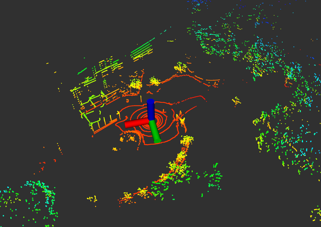 |
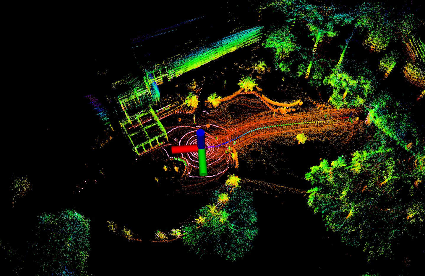 |
주변 SLAM 고수들에게 자문을 구한 결과, 이 행위는 LOAM 저자인 Ji Zhang씨가 LOAM 코드를 설계할 때 초기부터 camera와의 sensor fusion을 염두해두고 짠 것이어서 이렇게 좌표축 변환의 흔적이 남아있다고 한다 (진화적 퇴행과 같이 LOAM 계열 LiDAR odometry 코드에는 이런 좌표축 변환이 계속 남아있다). 그 증거를 코드 내부에서 확인할 수 있는데, 가장 대표적인 건 LiDAR odometry 코드임에도 불구하고 아래와 같이 visualization을 할 때 frame_id를 /camera로 사용하고 있다는 것이다.
void publishCloud()
{
    sensor_msgs::PointCloud2 laserCloudOutMsg;

    if (pubCornerPointsSharp.getNumSubscribers() != 0){
        pcl::toROSMsg(*cornerPointsSharp, laserCloudOutMsg);
        laserCloudOutMsg.header.stamp = cloudHeader.stamp;
        laserCloudOutMsg.header.frame_id = "/camera";
        pubCornerPointsSharp.publish(laserCloudOutMsg);
    }

    if (pubCornerPointsLessSharp.getNumSubscribers() != 0){
        pcl::toROSMsg(*cornerPointsLessSharp, laserCloudOutMsg);
        laserCloudOutMsg.header.stamp = cloudHeader.stamp;
        laserCloudOutMsg.header.frame_id = "/camera";
        pubCornerPointsLessSharp.publish(laserCloudOutMsg);
    }

    if (pubSurfPointsFlat.getNumSubscribers() != 0){
        pcl::toROSMsg(*surfPointsFlat, laserCloudOutMsg);
        laserCloudOutMsg.header.stamp = cloudHeader.stamp;
        laserCloudOutMsg.header.frame_id = "/camera";
        pubSurfPointsFlat.publish(laserCloudOutMsg);
    }

    if (pubSurfPointsLessFlat.getNumSubscribers() != 0){
        pcl::toROSMsg(*surfPointsLessFlat, laserCloudOutMsg);
        laserCloudOutMsg.header.stamp = cloudHeader.stamp;
        laserCloudOutMsg.header.frame_id = "/camera";
        pubSurfPointsLessFlat.publish(laserCloudOutMsg);
    }
}
이러한 축 변경에 대한 이유는 LeGO-LOAM 레포지토리 issue에서 열띄게 토의(?)했던 주제라는 것도 확인할 수 있다.
The original LOAM code has a lot of mysterious parts and you should probably not read it too much unless you want your eyes to bleed. The coordinate switching here probably has to do with projecting the lidar points in the camera frame. I believe that historically the “open source” LOAM was published as Ji Zhang was preparing V-LOAM.
(의역) 원본 LOAM 코드는 많은 미스터리한 부분이 있기 때문에 하나하나 다 알려하다 보면 눈에 피가 날 수도 있습니다
그걸 제가 하고 있습니다. 그러니 너무 꼼꼼히 이해하려 할 필요가 없습니다. 여기서의 좌표 전환은 아마도 카메라 프레임에 LiDAR 포인트를 투영하기 위함이라고 추측됩니다. 이는 LOAM 코드를 open했을 당시 Ji Zhang이 V-LOAM을 준비하고 있을 때여서 이렇게 역사적 흔적(?)이 남겨진 것이 아닌가 생각됩니다.
ii) 각 point의 relative time 계산
축을 ZYX로 변환한 후, 아래와 같이 상대적 시간을 구한다.
float ori = -atan2(point.x, point.z);
if (!halfPassed) {
    if (ori < segInfo.startOrientation - M_PI / 2)
        ori += 2 * M_PI;
    else if (ori > segInfo.startOrientation + M_PI * 3 / 2)
        ori -= 2 * M_PI;

    if (ori - segInfo.startOrientation > M_PI)
        halfPassed = true;
} else {
    ori += 2 * M_PI;

    if (ori < segInfo.endOrientation - M_PI * 3 / 2)
        ori += 2 * M_PI;
    else if (ori > segInfo.endOrientation + M_PI / 2)
        ori -= 2 * M_PI;
}

float relTime = (ori - segInfo.startOrientation) / segInfo.orientationDiff;
Tixiao님께는 죄송하지만, 이 부분은 수정되어야할 필요가 있다. 실제로 cout을 출력해보면 relTime이 0보다 작거나 1보다 큰 경우가 발생하게 된다 (NOTE: relTime은 첫 점과 끝 점이 관측된 시간을 기준으로 해당 point가 측정된 시간의 ratio를 나타내기 때문에 무조건 0과 1사이의 값이여야 함). 왜 이런 현상이 일어나나 했더니, 현재 ImageProjection 과정에서 range image로 projection -> image 평면에서 인덱스 순으로 segmentedCloud를 할당했기 때문에 현재 for문의 순서를 통해 halfPassed인지 아닌 지 판별하는게 말이 안 된다 (이전에 이미 설명했듯이, segmentedCloud의 순서는 (0, 0)->(0, 1)->…->(0, 1799)->(1, 0)->…->(15, 1799)순으로 서치하면서 유효한 points만 push_back하는 식으로 되어있음). 즉 아래의 그림과 같이 original data는 빨간 화살표의 방향을 따라 획득되었으나 현재 segmentedCloud 방향은 image projection->unprojection 과정으로 인해 초록색 화살표를 따라서 진행되기 때문에 halfPassed를 판별할 수 없다.
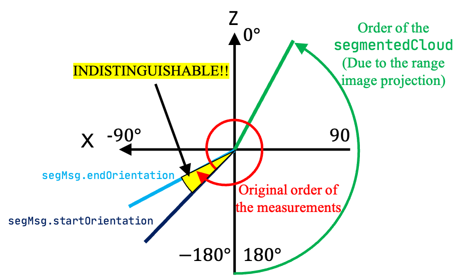
따라서, 본 relTime은 아래와 같이 구해져야 한다고 생각한다 (100% 저의 주관적 해석입니다).
float relTime;
float endOriCorrected = segInfo.endOrientation - (M_PI * 2);
if ( (ori > segInfo.startOrientation) && (ori < endOriCorrected) ||
        ( (endOriCorrected > M_PI) && ((ori > segInfo.startOrientation) || (ori + 2 * M_PI < endOriCorrected)) ) ) {
    // We do not discern whether the point is measured when `relTime` is 0~0.0451(17deg/360) or 0.955~1.0 (The indistinguishable part in the upper figure)
    relTime = 0.0;
} else {
    if (ori <= segInfo.startOrientation) {
        relTime = (2 * M_PI - (segInfo.startOrientation - ori) ) / segInfo.orientationDiff;
    } else {
        relTime = (ori - segInfo.startOrientation) / segInfo.orientationDiff;
    }
}
다행히 이 문제는 후속연구인 LIO-SAM에서는 deskewing을 ImageProjection 단에서 하는 것으로 변경되어 완벽히 해결되어 있다 Tixiao Shan…그는 신이야!. 그렇게 relTime을 계산한 후, 아래와 같이 point의 intensity에 해당 포인트가 취득된 second 단위의 시간이 할당된다.
point.intensity = int(segmentedCloud->points[i].intensity) + scanPeriod * relTime;
여기서 주의할 것은 intensity의 int 파트에는 ImageProjection에서 할당했던 rowIdn (LiDAR sensor의 channel id)이 저장되어 있다. 이 rowIdn은 향후 feature를 추출할 때 feature들이 인접하게 존재하는 지 판단할 때 활용된다.
calculateSmoothness()
그 후 아래와 같이 curvature 값을 구한다. 그리고 모든 valid segments에 대응하는 pixel은 ‘cloudNeighborPicked[i] = 0’, ‘cloudLabel[i] = 0’로 초기화가 되고 여기서 cloudNeighborPicked[i]는 향후 edge, corner features를 추출할 때 해당 pixel을 후보군으로 쓸지 말지를 결정한다 (뒤의 markOccludedPoints() 함수 참고). 참고로 1로 할당되면 향후 해당 pixel 값이 feature로서 사용되지 않음을 의미한다.
void calculateSmoothness()
{
    int cloudSize = segmentedCloud->points.size();
    for (int i = 5; i < cloudSize - 5; i++) {

        float diffRange = segInfo.segmentedCloudRange[i-5] + segInfo.segmentedCloudRange[i-4]
                        + segInfo.segmentedCloudRange[i-3] + segInfo.segmentedCloudRange[i-2]
                        + segInfo.segmentedCloudRange[i-1] - segInfo.segmentedCloudRange[i] * 10
                        + segInfo.segmentedCloudRange[i+1] + segInfo.segmentedCloudRange[i+2]
                        + segInfo.segmentedCloudRange[i+3] + segInfo.segmentedCloudRange[i+4]
                        + segInfo.segmentedCloudRange[i+5];

        cloudCurvature[i] = diffRange*diffRange;

        cloudNeighborPicked[i] = 0;
        cloudLabel[i] = 0;

        cloudSmoothness[i].value = cloudCurvature[i];
        cloudSmoothness[i].ind = i;
    }
}
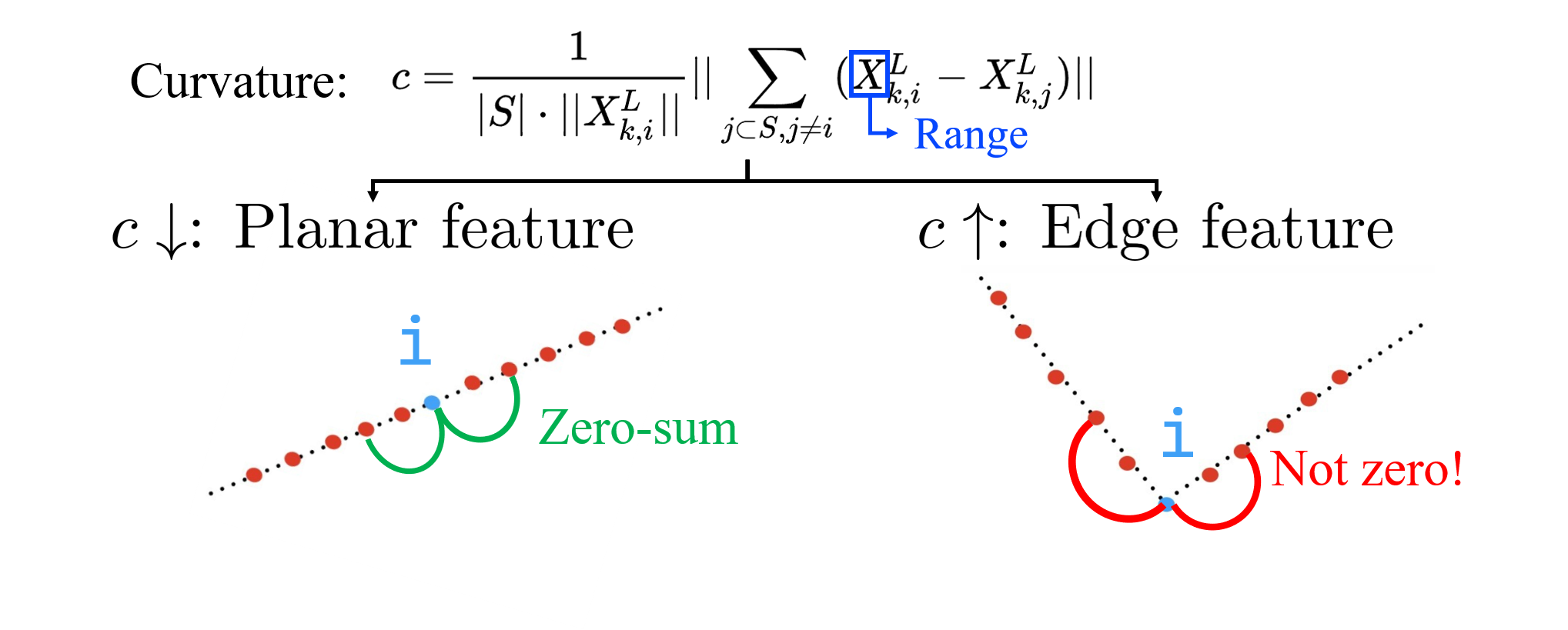
Curvature 값은 아래와 같이 기하학적으로 해석할 수 있는데, 양 근처의 points들간의 거리의 합이 0에 가까운 경우에는 해당 포인트가 평평하다고 해석할 수 있고 (cloudCurvature[i]가 작음) 양 근처의 point들간의 거리의 합이 0이 안 되는 경우에는 얖 옆이 다른 경사로 이루어져 있거나 아래 그림과 같이 돌출되어 있다고 해석할 수 있다 (cloudCurvature[i]가 큼).
추가적으로, 이 글을 정리하다가 새롭게 안 사실인데, 현재 코드 상에서 i-k와 i+k는 (k=1, 2, 3, 4, 5)는 인접한 픽셀 값이 아니다!. 앞에서도 말했듯이 ImageProjection의 cloudSegmentation() 함수에서 유효한 point들만 range image의 인덱스 순으로 아래와 같이 차곡차곡 segmentedCloud가 할당되는데,
// In `cloudSegmentation()` function in `imageProjection.cpp`
for (size_t j = 0; j < Horizon_SCAN; ++j) {
    if (labelMat.at<int>(i,j) > 0 || groundMat.at<int8_t>(i,j) == 1){
        // outliers that will not be used for optimization (always continue)
        if (labelMat.at<int>(i,j) == 999999){
            if (i > groundScanInd && j % 5 == 0){
                outlierCloud->push_back(fullCloud->points[j + i*Horizon_SCAN]);
                continue;
            }else{
                continue;
            }
        }
        // majority of ground points are skipped
        if (groundMat.at<int8_t>(i,j) == 1){
            if (j%5!=0 && j>5 && j<Horizon_SCAN-5)
                continue;
        }
        // mark ground points so they will not be considered as edge features later
        segMsg.segmentedCloudGroundFlag[sizeOfSegCloud] = (groundMat.at<int8_t>(i,j) == 1);
        // mark the points' column index for marking occlusion later
        segMsg.segmentedCloudColInd[sizeOfSegCloud] = j;
        // save range info
        segMsg.segmentedCloudRange[sizeOfSegCloud]  = rangeMat.at<float>(i,j);
        // save seg cloud
        segmentedCloud->push_back(fullCloud->points[j + i*Horizon_SCAN]);
        // size of seg cloud
        ++sizeOfSegCloud;
    }
}
그 결과, 아래의 그림과 같이 i-k와 i+k는 가장 가까운 유효한 pixel를 가리킨다는 것을 아래와 같이 나타낼 수 있다. 심지어는 우리의 생각과는 다르게 range image 끝 쪽에서는 위/아래쪽 채널이 비교가 된다 (근데 후의 extractFeatures()에서 각 channel 별 가장 앞/뒤 5개는 feature로 선별하지 않게 되어있어 문제 없긴 하다 그럼 여기서도 그냥 뽑지 말지).
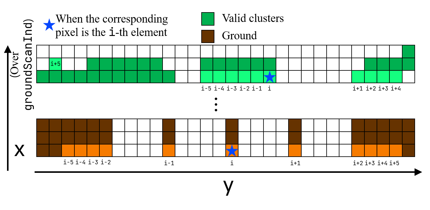
향후 implementation을 개선해야할 일이 있으면 i-k과 i+k가 i 기준으로 충분히 가까이 있어야 한다는 조건을 추가해야할 것 같다 (하지만 clustering으로 인해 대체로 valid segments들은 붙어있기 때문에, 기존 코드 상의 방식대로 smoothness를 평가해도 말이 됨).
markOccludedPoints()
그 후, valid segments 상에서 masking을 진행한다. 코드는 아래와 같다.
void markOccludedPoints()
{
    int cloudSize = segmentedCloud->points.size();

    for (int i = 5; i < cloudSize - 6; ++i){

        float depth1 = segInfo.segmentedCloudRange[i];
        float depth2 = segInfo.segmentedCloudRange[i+1];
        int columnDiff = std::abs(int(segInfo.segmentedCloudColInd[i+1] - segInfo.segmentedCloudColInd[i]));
        // Case 1
        if (columnDiff < 10){
            if (depth1 - depth2 > 0.3){
                cloudNeighborPicked[i - 5] = 1;
                cloudNeighborPicked[i - 4] = 1;
                cloudNeighborPicked[i - 3] = 1;
                cloudNeighborPicked[i - 2] = 1;
                cloudNeighborPicked[i - 1] = 1;
                cloudNeighborPicked[i] = 1;
            }else if (depth2 - depth1 > 0.3){
                cloudNeighborPicked[i + 1] = 1;
                cloudNeighborPicked[i + 2] = 1;
                cloudNeighborPicked[i + 3] = 1;
                cloudNeighborPicked[i + 4] = 1;
                cloudNeighborPicked[i + 5] = 1;
                cloudNeighborPicked[i + 6] = 1;
            }
        }

        // Case 2
        float diff1 = std::abs(float(segInfo.segmentedCloudRange[i-1] - segInfo.segmentedCloudRange[i]));
        float diff2 = std::abs(float(segInfo.segmentedCloudRange[i+1] - segInfo.segmentedCloudRange[i]));

        if (diff1 > 0.02 * segInfo.segmentedCloudRange[i] && diff2 > 0.02 * segInfo.segmentedCloudRange[i])
            cloudNeighborPicked[i] = 1;
    }
}
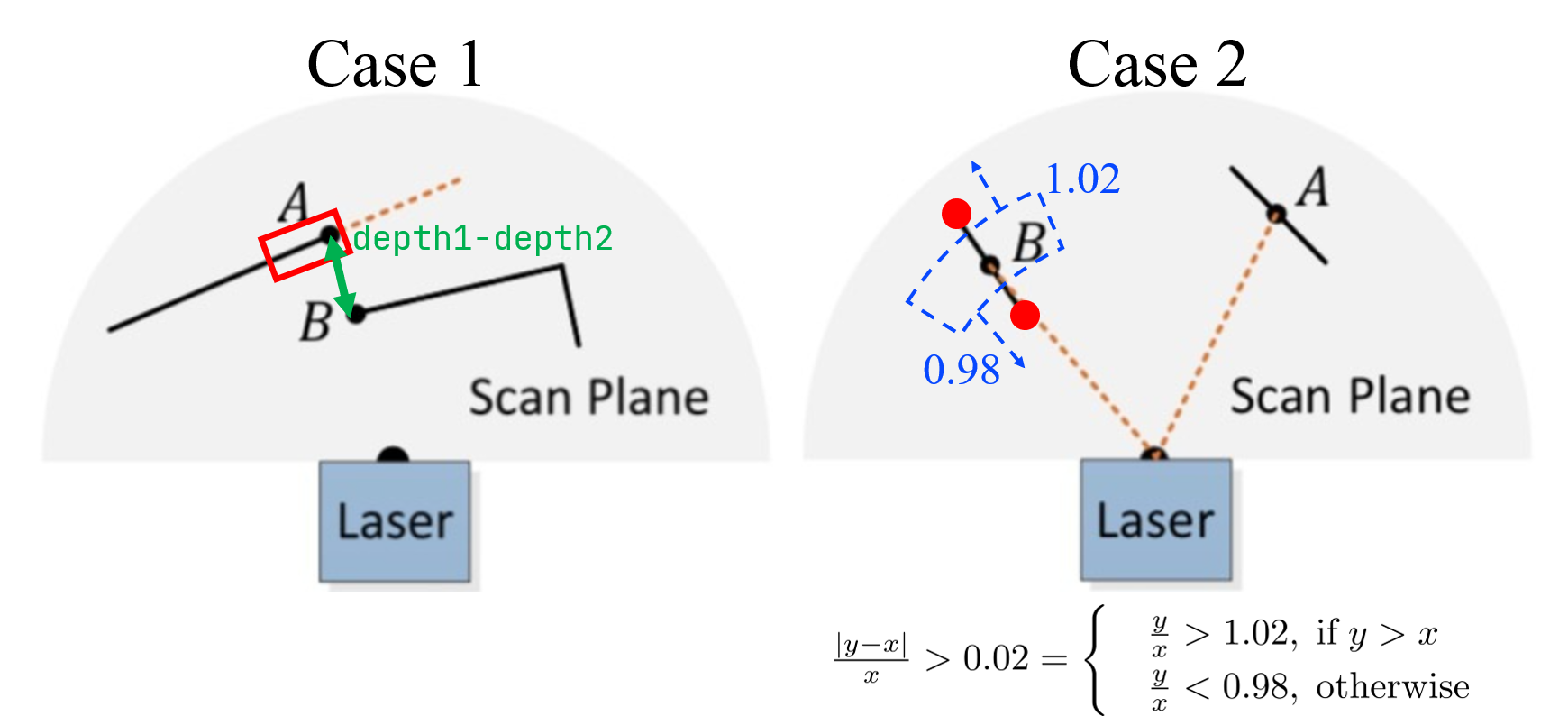
현 논문에서는 아래와 같은 두 케이스에 대해서 masking을 씌운다.
- Case1: 인접한 두 포인트가 가까이 있지만, i.e
columnDiff < 10, range의 차가 너무 많이 나는 경우에는 occlusion이 일어났다고 판단한다 (아래 그림의 Case 1). - Case2: i번째 point를 기준으로 양 옆의 가장 가까운 valid segments와 상대적 거리차가 어느정도 나는지 확인한다. 그래서 i-1번째와 i+1번 째 모두 다 i를 기준으로 상대적 거리가 꽤 차이나게 위치하고 있으면, i.e. range * 1.02 초과거나 range * 0.98 미만이면, i 번째 point를 feature 후보군으로 여기지 않는다 (아래 그림의 Case 2).
LeGO-LOAM의 line-by-line 설명 시리즈입니다.
- LeGO-LOAM-Line-by-Line-1.-Introduction: Preview and Preliminaries
- LeGO-LOAM-Line-by-Line-2.-ImageProjection-(1): Range Image Projection & Ground Removal
- LeGO-LOAM-Line-by-Line-2.-ImageProjection-(2): Cloud Segmentation using Clustering
- LeGO-LOAM-Line-by-Line-3.-FeatureAssociation-(1): Ready for Feature Extraction
- LeGO-LOAM-Line-by-Line-3.-FeatureAssociation-(2): Corner and Planar Feature Extraction
- LeGO-LOAM-Line-by-Line-3.-FeatureAssociation-(3): Relative Pose Estimation via Two-stage Optimization